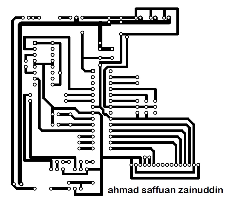
Design a Printed Circuit Board (PCB) layout of the system is important to combine all the components that are used in one circuit. To design this PCB layout of this DICM system, the DipTrace software was used. In this software, the main component is the Atmega 328 which acts as the control center or the brain of the system was added first before starting to design the PCB of this system. After that, other components such as IR sensor, solenoid motor, DC gear motor, DC motor sprinkler, LCD and buzzer was added together to the main component which is Atmega 328. The design a PCB layout of DICM system is shown in the figure below.
By design this PCB layout, we know how to put or added the components and adjust the component and the tracks on the circuit board to make sure there are no contact with each other. This is important before we print the real PCB circuit and start with etching process.
Before this, I had shown the schematic diagram of this DICM system. But now, I will add some component to my DICM system which is Liquid Crystal Display (LCD). The function of LCD that was added to this system is to show if there are some notification to the user of this DICM system. For example of the notification if there are run out of fertilizer and pesticide on the system. This added component is useful to give the information to the user. The new schematic design of this DICM system is shown in the figure below.
By adding this LCD, it will give benefits to the user about their system.